Main-Type K
Main-Type K
If a force is applied on the lockedgas spring, the locking remains rigid up to the mechanical strength of the gas spring. If a force isapplied in compressed direction, the spring remains rigid until the force of the pressure on the floatingpiston is exceeded (locking force). If this occurs, thepiston rod inserts a little bit which may look like a overload safety device.
Starre Blockierung in Auszugrichtung, einschiebend bedingt starre Gasfeder
Hier erfolgt die Blockierung in einem Ölraum, der durch einen schwimmenden Trennkolben vom Gasraum getrennt ist. Wird die blockierte Gasfeder auf Zug belastet, ist “nur nicht komprimierbares Öl” zwischen Kolben und Führungsstück. Die Blockierung der Gasfeder bleibt starr bis zur mechanischen Festigkeit. In Einschubrichtung bleibt die Blockierung solange starr, bis die Kraft des Gasfeder-Fülldruckes auf den Trennkolben überschritten wird (Blockierkraft der Gasfeder).
Mögliche Artikel-Nr.:
- K0 = MF10x1x18
- O0 = MF14x1,5×20
- W0 = MF 8x1x16
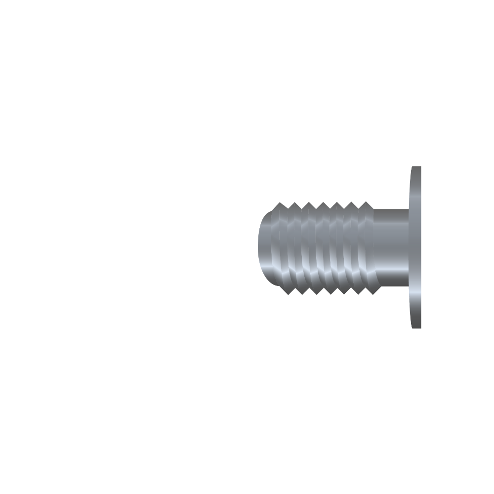
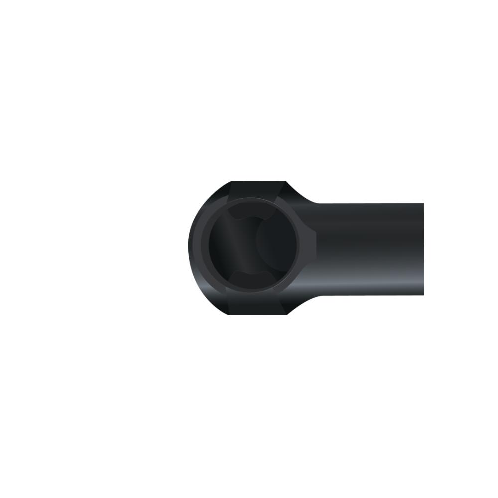
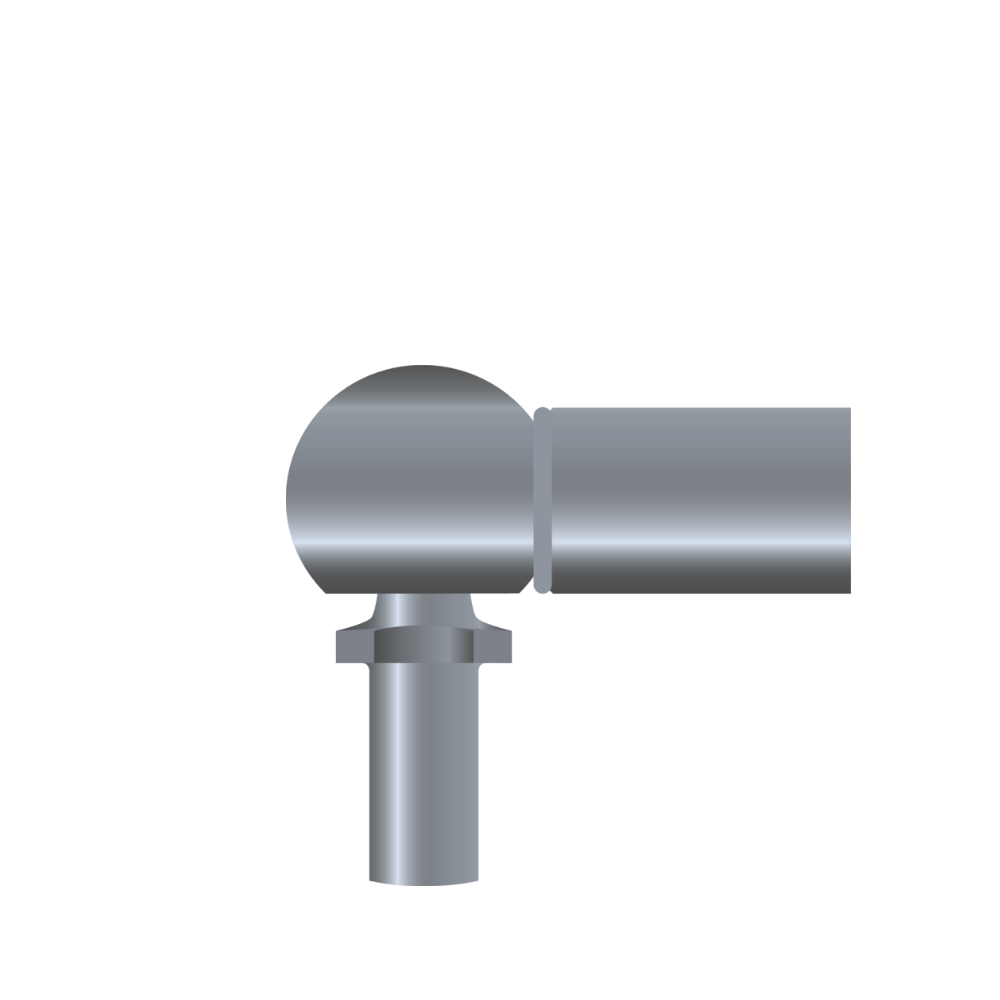
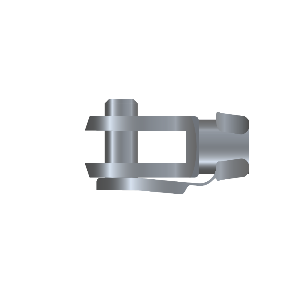
- siehe Anschlussteile
- K
- – = normal
- 0 = schnell
- 7 = langsam
- K = Kurzauslösung (Auslöseweg < 1 mm anstatt < 3,5 mm)
- B = Besonderheit
- N = Niro
- 6= 6/15
- C= 6/19
- D= 6/22
- 0= 8/19
- 1= 8/22
- E= 8/28
- 2= 10/22
- 3= 10/28
- A= 10/40
- 5= 14/28
- B= 14/40
- 10-150
- 10-150
- 10-150
- 10-300
- 10-300
- 10-300
- 10-500
- 10-500
- 10-500
- 30-700
- 30-700
- Hub x 2,62 +57
- Hub x 2,42 +57
- Hub x 2,41 +65
- Hub x 2,29 +65
- Hub x 2,29 +66
- Hub x 2,20 +66
- Hub x 2,73 +73
- Hub x 2,53 +73
- Hub x 2,27 +73
- Hub x 2,52 +74
- Hub x 2,37 +74
- Hub x 2,19 +74
- Hub x 2,33 +78
- Hub x 2,24 +78
- Hub x 2,13 +78
- Hub x 2,81 +83
- Hub x 2,58 +83
- Hub x 2,30 +83
- Hub x 2,52 +77
- Hub x 2,36 +77
- Hub x 2,19 +77
- Hub x 2,21 +99
- Hub x 2,15 +99
- Hub x 2,08 +99
- Hub x 2,97 +93
- Hub x 2,69 +93
- Hub x 2,32 +93
- Hub x 2,43 +99
- Hub x 2,31 +99
- Hub x 2,15 +99
- 35
- 50
- 35
- 50
- 35
- 50
- 35
- 50
- 100
- 35
- 50
- 100
- 35
- 50
- 100
- 35
- 50
- 100
- 35
- 50
- 100
- 35
- 50
- 100
- 35
- 50
- 100
- 35
- 50
- 100
- *siehe Unten
- 50-400
- 50-400
- 50-400
- 40-700
- 40-700
- 40-700
- 50-1300
- 50-1300
- 50-1300
- 150-2600
- 150-2600
- verringerte Blockierkraft
- verringerte Blockierkraft
- verringerte Blockierkraft
- verringerte Blockierkraft
- verringerte Blockierkraft
- verringerte Blockierkraft
- verringerte Blockierkraft
- verringerte Blockierkraft
- verringerte Blockierkraft
- verringerte Blockierkraft
- verringerte Blockierkraft
- 7.000
- 10.000
- 10.000
- 10.000
- 10.000
- 4 x F1
- 5,6 x F1
- 9 x F1
- 3,6 x F1
- 5,8 x F1
- 13 x F1
- 2,9 x F1
- 6,6 x F1
Durch die Indexnummer – nur für Ihre Nachbestellung erforderlich – können wir einmal gefertigte Gasfedern exakt reproduzieren. Sie erhalten den Indexcode mit der Auftragsbestätigung/Rechnung Ihrer Gasfeder.
EL1
Berechnung der Gasfeder-Einbaulänge erfolgt mit ausgefahrener Kolbenstange. Die Länge der gewünschten Anschlussteile zur Ermittlung der Gesamteinbaulänge der Gasfeder hinzurechnen.
EL2
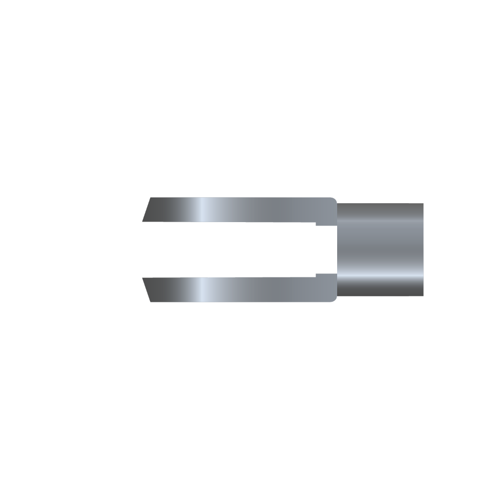
Einbaulänge EL2 = Gasfeder ohne Gelenkaugen / ohne Gewindelänge gemessen.
Bansbach Anschlussteile


Bansbach Auslösesysteme
Hebelauslösungen

Bowdenzug-Auslösungen

Hydraulik-Auslösungen

- 1Gasfeder-Auslösekopf Standard
- 2Drehpunkt
- 1a1a Auslösehebel (Auslöserichtung hin zur Feder)
- 2a1a Auslösehebel (Auslöserichtung hin zur Feder)
- 1bAuslösehebel (Auslöserichtung weg von der Feder)
- 2bAuslösehebel (Auslöserichtung weg von der Feder)
construction
- 20AK08M8*1
- 20AKXXMXX
- 20AK10M10*1
- 20AK12M10*1
- 20AK12M14*1,5
- 20AK14M14*1,5
inpull direction
- 7.000
- 7.000
- 12.000
- 12.000
- 12.000
- 12.000
- 37
- 37
- 54
- 54
- 54
- 54
- 30
- 30
- 39
- 39
- 39
- 39
- 38
- 40
- 50
- 50
- 50
- 50
- R8,5
- R8,5
- R14
- R14
- R14
- R14
- 8,1-0,05
- 10,1-0,05
- 10,1-0,05
- 12,1-0,05
- 12,1-0,05
- 14,1-0,05
- 17
- 17
- 21
- 21
- 21
- 21
- SW11
- SW11
- SW14
- SW14
- SW14
- SW14
- 20
- 20
- 26
- 26
- 26
- 26
- 38.5
- 38.5
- 53
- 53
- 53
- 53
- M8*1
- M10*1
- M10*1
- M10*1
- M14*1.5
- M14*1.5
nut
- SW13
- SW17
- SW17
- SW17
- SW19
- SW19
mm
- 9
- 7
- 8
- 8
- 8
- 8
Bansbach Downloads
Bansbach Einbauempfehlung
-
Bansbach-Gasfedern können bei Umgebungstemperaturen von -30°C bis +80°C eingesetzt werden. Für andere Temperaturbereiche (bis -55°C oder bis +200°C) stehen spezielle Dichtungssätze zur Verfügung. Für Niedrig-Temperatur-Bereiche ist eine detaillierte Abstimmung der Anforderungen notwendig. Die Umgebungstemperatur hat Einfluss auf die Gasfeder-Charakteristik. Veränderungen der Ausschubkraft sowie der Dämpfungseigenschaften sind zu erwarten und sollten vorab unter Anwendungsbedingungen getestet werden. Gasfedern nicht überhitzen oder in offenes Feuer legen! Auch sonstige Umgebungsbedingungen können wesentlichen Einfluß auf die Lebensdauer haben. Bitte Schutzmaßnahmen in Betracht ziehen.
-
Gasfedern sind mit reinem Stickstoff gefüllt. Stickstoff ist ein inertes Gas, brennt nicht, explodiert nicht und ist nicht giftig. Aber: Gasfedern haben einen sehr hohen Innendruck (bis ca. 300 bar). Gasfedern dürfen keinesfalls ohne Anleitung geöffnet werden!
-
Entsorgung / Recycling: Gasfedern bestehen vorwiegend aus Metall und können der stofflichen Wiederverwertung zugeführt werden. Aber die Gasfedern müssen voher drucklos sein. Bitte fordern Sie unsere Entsorgungsvorschriften für Gasfedern an.
-
Alle Gasfedern werden von Werkseite mit dem Warnhinweis „Nicht öffnen, hoher Druck“, der Teilenummer und dem Herstellungsdatum versehen / etikettiert. Werden diese Daten unleserlich (Entfernen des Etikettes, Überlackieren od. sonstige äußerliche Einflüsse) erlischt die Gewährleistung für daraus entstandene Schäden. Garantieleistungen sind nicht mehr möglich.
-
Bansbach-Gasfedern dürfen im Allgemeinen als Endanschlag in beiden Richtungen benutzt werden. Dabei dürfen folgende Richt werte nicht überschritten werden.
Baureihe- 3/8
- 3/10
- 4/12
- 6/15
- 6/15 Niro
- 6/19
- 8/19
- 8/19 Niro
- 8/20 Alu
- 8/22
- 8/28
- 10/22
- 10/22 Niro
- 10/28
- 10/28 Niro
- 10/40
- 12/28
- 12/40
- 14/28
- 14/28 Niro
- 14/40
- 16/28
- 20/40
max. Kraft (N)- 600
- 600
- 1.500
- 2.500
- 1.750
- 2.000
- 5.000
- 3.000
- 3.500
- 5.000
- 7.000
- 5.500
- 3.000
- 8.500
- 6.500
- 7.000
- 9.250
- 12.500
- 7.000
- 7.000
- 6.250
- 15.000
- 10.000
Dies gilt nicht für blockierbare Gasfedern und Zugfedern!
Achtung: Die Angaben beziehen sich auf den mittleren Druck be reich einer jeweiligen Bau reihe. Manche Anschlussteile, z.B. Win kel gelenke sind für diese Grenz bereiche nur bedingt geeignet.
Bei besonders hohen End an schlags kräften sowie bei dauerhafter Belastung ist ein zusätzlicher mechanischer Endanschlag empfehlenswert. Im Grenzbereich bzw. bei dauerhafter Beanspru chung bitten wir um Rücksprache mit Bansbach easylift.
-
Gasfedern sollten grundsätzlich mit der Kolbenstange nach unten eingebaut werden. Diese Lage garantiert beste Dämpfungseigenschaften. Nur Bansbach-Gasfedern haben eine integrierte Fettkammer, die auch einen lageunabhänigigen Einbau zuläßt.
-
Die Gasfedern dürfen bei ihrer Funktion keinen Verkantungen und Seitenkräften ausgesetzt sein (vorzeitiger Verschleiß, Abbiegen von Kolbenstangen). Gegebenenfalls Einbau der Gasfeder überprüfen und geeignete Anschlußstücke vorsehen.
-
Sollten Gasfedern durch äußere Einwirkung (Unfall, Kollision, extreme Überlastung,…) sichtbar beschädigt sein (abgebrochene oder deformierte Anschlussteile, verbogene Kolbenstange, verbeulter Zylinder,…), muss vor dem Ausbau der Gasfeder oder sonstiger Handhabung der Druck abgelassen werden.
Beachten Sie bitte dazu unsere Entsorgungsvorschriften! -
Gasfedern sind wartungsfrei! Kolbenstange nicht fetten, ölen etc.
-
Die Kolbenstange ist vor Schlageinwirkung, Kratzern und Verschmutzung – besonders Farbauftrag – zu schützen. Das Zylinderrohr darf nicht deformiert werden. Beschädigungen der Oberfläche zerstören das Dichtungssystem der Gasfeder.
-
Bansbach-Gasfedern können in beliebiger Lage gelagert werden. Druckverlust der Gasfeder durch lange Lagerhaltung ist nicht zu erwarten. Es liegen keine negativen Erfahrungswerte vor. Aber es können Festklebeeffekte auftreten, die bei erstmaliger Betätigung der Gasfeder einen höheren Kraftaufwand erfordern (Losbrechkraft).
-
Gewährleistungsansprüche verfallen prinzipiell spätestens 1 Jahr nach Fertigungsdatum der Gasfeder. Herstellungsfehler bzw. Qualitätsmängel an der Gasfeder sind sofort feststellbar. Falls Sie aus einem bestimmten Grund nicht mit der gelieferten Qualität der Gasfeder zufrieden sind, bitten wir um unverzügliche Rücksendung. Begründung und Rechnungskopie beifügen!
-
Werden Gasfedern zur Detailprüfung eingesandt, wird damit das Einverständnis zur Zerstörung dieses Teiles erteilt, das Eigentumsrecht erlischt damit. Eine Rücklieferung von Einzelkomponenten ist nicht möglich. Gegebenenfalls Einsendungen markieren mit z.B. „Für Funktionsprüfung und mit der Bitte um Rücksendung“. Liegt kein Widerspruch vor, werden eingesandte Gasfedern 1 Woche nach Bekanntgabe des Prüfungsergebnisses entsorgt.
Grundsätzlich gilt: Für unberechtigte Reklamationen behalten wir uns das Recht vor, eine Kostenpauschale oder die tatsächlichen Kosten für Bearbeitung und Entsorgung zu berechnen. -
Bansbach-Gasfedern werden – aus meist lagerhaltigen Bauteilen – auftragsbezogen gefertigt. Stornierung, nachträgliche Änderung, Umtausch oder Rückgabe ist daher nicht möglich.
-
Bansbach-Gasfedern sind für höchste Anforderungen und größtmögliche Zuverlässigkeit konstruiert und getestet worden. Einbauempfehlungen und unsere umfangreiche Beratung unterstützen Sie bei der Auswahl Ihrer individuellen Gasfedern.
Aber: Die Eignungsprüfung für den jeweiligen Anwendungsfall obliegt immer dem Anwender! Für den Anwendungsfall nicht geeignete und fehlerhafte Produkte dürfen nicht verwendet werden. Für Funktionalität und Lebensdauer Ihres Endproduktes schließen wir daher jegliche Haftung aus. -
Dämpfungseigenschaften können Schwingungen erzeugen die in der Anwendung einen Resonanzkörper finden und dabei Geräusche verursachen. Kleine Änderungen am Einbau, an den Befestigungen oder an der Abstimmung können Abhilfe schaffen.
-
Innerhalb der dargestellten Bereiche können Sie Ihre optimale Abmessung selbst auswählen. Als Toleranz für die Einbaulängen gilt allgemein ± 2,5 mm, innerhalb einer Serienfertigung gilt eine Fertigungstoleranz von max. ± 1 mm. Bei hohen Ansprüchen an Haltbarkeit und Stabilität vermeiden Sie bitte die Kombination: Kleiner Durchmesser + langer Hub + hohe Kraft.
Do you need help?
We are there for you
Contact personthe product is precisely adapted to your requirements in order to ensure optimal function. We are happy to support and advise you in the selection of the right product.
With our „Technical Support“ you have a direct line to our technicians, who will competently assist you. If you have any questions about offers, availability or prices, our commercial support will be happy to assist you.

Step by step to the individual product
The Bansbach gas spring configurator offers
you the possibility to put together your individual
gas spring from various components
even more easily and quickly.

Bansbach easylift
- » High-quality stainless steel material (V4A, AISI No. 316L)
- » Water resistant
- » Suitable for food, chemical and seawater applications
- » Connecting parts also made of stainless steel
Bansbach
Quality
Bansbach products are manufactured exclusively from high-quality, environmentally friendly materials. By continuously monitoring raw materials, carrying out test programmes and monitoring quality during the manufacturing process, consistently high quality can be guaranteed.


FAQs
Aus welchem Material bestehen Bansbach-Gasfedern?
Gasfedern bestehen im wesentlichen aus Kolbenstange, Zylinderrohr, Anschlussteile, Drehteile, Dichtungen, Öl, Fett und Stickstoff. Kolbenstange und Zylinderrohr sind aus Stahl und werden in unserem Hause CeramPro®- bzw. pulverbeschichtet. Anschlussteile und Drehteile sind aus bleifreiem Stahl oder bleifreiem Aluminium.
Dichtungen, Öle, Fette enthalten keine Substanzen, die auf der Liste der kritischen oder gefährlichen Stoffe stehen. Stickstoff ist ein inertes Gas, das weder brennt noch sonstige Gesundheitsgefahren in sich birgt. Bansbach-Gasfedern entsprechen deshalb den aktuellen und soweit uns bekannt auch den geplanten Gesetzen und Verordnungen.
Sie entsprechen zum Beispiel der RoHS Directive, WEEE Directive, den Richtlinien 2003/11/EC, 2002/95/EC, 2002/96/EG. Sie fallen nicht unter die Richtlinien 94/9/EG, 97/23/EG, und 98/37/EG, auch nicht unter die UN 3164, TRGS 220 und UL 60601-1.
Die Prüfung, ob Bansbach-Gasfedern im Endprodukt den nationalen oder internationalen Gesetzen und Vorschriften entsprechen, bleibt in der Verantwortung unserer Kunden bzw. des Anwenders.
Dürfen Gasfedern im Hausmüll entsorgt werden?
Nein, Gasfedern bestehen vorwiegend aus Metall. Bitte unsere Entsorgungsvorschriften beachten.
In welchen Farben sind Bansbach-Gasfedern erhältlich?
Grundsätzlich wird die Kolbenstange und der Zylinder in schwarzer Ausführung geliefert (Standard).
Auf Nachfrage sind unsere Zylinder in sämtlichen RAL-Farben verfügbar. Ausnahme: Edelstahl
In welchen Temperaturbereichen können Bansbach Gasfedern eingesetzt werden?
Bei Umgebungstemperaturen von –30°C bis +80°C.
Für andere Temperatubereiche (bis –55°C oder bis +200°C) stehen spezielle Dichtungssätze zur Verfügung.
Ist die Ausschubkraft der Gasfeder temperaturabhängig?
Die Ausstellkraft der Gasfeder ändert sich physikalisch bedingt je 10°C um ca. 3,3% (Basis + 20°C)
Kann die Geschwindigkeit / Dämpfung der Gasfeder beeinflusst werden?
Durch Wahl der entsprechenden Düsenbohrung und Ölviskosität kann die Geschwindigkeit und Dämpfung der Gasfeder an die Anwendung angepasst werden.
Kann eine auf Kundenwunsch gefertigte Gasfeder zurückgegeben werden?
Bansbach-Gasfedern werden – aus meist lagerhaltigen Bauteilen – auftragsbezogen gefertigt. Stornierung, Umtausch oder Rückgabe ist daher nicht möglich.
Bei kostenloser Anlieferung übernehmen wir gerne die Entsorgung – ohne Berechnung – für Sie.
Kann eine Gasfeder repariert werden?
Nein, da es sich um ein geschlossenes System handelt, das unter hohem Druck steht und nicht geöffnet werden darf.
Können Gasfedern in der Lebensmittelindustrie eingesetzt werden?
Mit den hochwertigen Edelstahlgasfedern in V4A werden die hohen Anforderungen der Lebensmittelindustrie erfüllt. Optional ist lebensmittelechtes Öl (FDA- Öl) erhältlich.
Muss eine Gasdruckfeder gewartet werden?
Nein, Bansbach-Gasfedern sind wartungsfrei. Grundsätzlich darf die Kolbenstange nicht gefettet oder geölt werden.
Muss eine Gasfeder vor Verschmutzung geschützt werden?
Die Kolbenstange ist vor Schlageinwirkung, Kratzern und Verschmutzung – besonders Farbauftrag – zu schützen. Beschädigungen der Oberfläche zerstören das Dichtungssystem. Gegebenenfalls sollte ein Abstreifer oder ein Schutzrohr vorgesehen werden.
Müssen Bansbach-Gasfedern mit der Kolbenstange nach unten zeigend gelagert werden?
Bansbach-Gasfedern können in beliebiger Lage gelagert werden.
Sind Bansbach Gasfedern ROHS konform?
Ja, sie sind uneingeschränkt ROHS konform und erfüllen darüber hinaus alle uns bekannten Richtlinien, Export-/Importbestimmungen und Ziele sonstiger Firmenprogramme.
Was bedeutet die Indexnummer (z.B. –001/100 N) am Ende der Artikelbezeichnung der Gasfeder?
Dies ist ein von Bansbach intern vergebener Code zur eindeutigen Reproduzierbarkeit der Gasfeder.
Welche Hublängen sind für die Gasfedern möglich?
Je nach Baureihe und Bauart der Gasfeder ist die Hublänge zwischen 10 mm und 1000 mm frei wählbar.
Welche Lebensdauer / Laufleistung kann ich von einer Bansbach-Gasfeder erwarten?
Im Durchschnitt werden Bansbach-Gasfedern auf 50.000 – 100.000 Doppelhub ausgelegt.
Je nach Ausführung, Einbau und Nutzhub können auch mehrere 100.000 Hübe erreicht werden.
Wie finde ich meinen persönlichen Ansprechpartner?
Bansbach easylift GmbH
Bararossastrasse 8
D-73547 Lorch
Phone: +49 (0) 7172/9107-0
Fax: +49 (0) 7172/9107-44
E-Mail: info@bansbach.de
Einen Ansprechpartner vor Ort finden Sie hier:
Wie hoch ist das Gewicht einer Gasfeder?
Aufgrund des breiten Lieferprogramms variieren die Gewichte stark.
Durchmesser Kolbenstange / Zylinder:
Ø3/8; Ø4/12; Ø6/15; Ø6/19; Ø6/22; Ø8/19; Ø8/22
Gewicht
100 g – 500 g
———-
Durchmesser Kolbenstange / Zylinder
Ø8/28; Ø10/22; Ø10/28; Ø12/28; Ø14/28
Gewicht
200 g – 1000 g
———-
Durchmesser Kolbenstange / Zylinder
Ø16/28; Ø10/40; Ø12/40; Ø14/40; Ø20/40; Ø30/70
Gewicht
500 g – 8000 g
Wie hoch kann der Innendruck einer Gasfeder sein?
Abhängig von Baureihe und gewünschter Ausschubkraft kann dieser bis zu ca. 300 bar betragen.

With our „Technical Support“ you have a direct line to our technicians, who will competently assist you. If you have questions about offers, availability or prices, our commercial support will be happy to assist you.

