Lockable gas traction spring
Gas traction springs – according to your requirements
In many technical fields, there are structural restrictions which can be solved by an easylift gas traction springs or lockable gas traction springs. In one respect can mechanical comprehensive force deflec tions be saved and a well-designed integration in the most different products is also possible.
Description
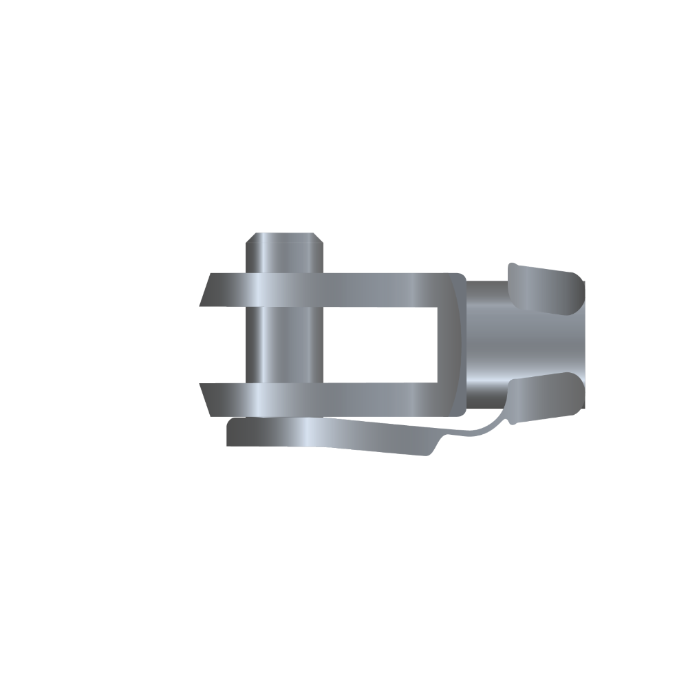
Bansbach lockable gas traction spring
Lockable gas traction springs are continuously adjustable over the whole stroke. The lockable gas traction spring can be released by pushing the release pin. When the piston valve opens, gas or oil can flow through the piston and the piston rod will be inserted. Due to the high reliability, this type of spring is preferentially used for medical equipment.
Function:
Pull-in force:
100-4000 N (depends on diameter piston rod/cylinder)
Locking force in push and pull direction:
max. 7.000 N
Stroke:
10-350 mm
Release travel:
Short release possible release travel < 1mm
Diameter
piston rod/cylinder:
piston rod/cylinder:
10/28 and 14/40
Speed/damping:
normal, fast, slow
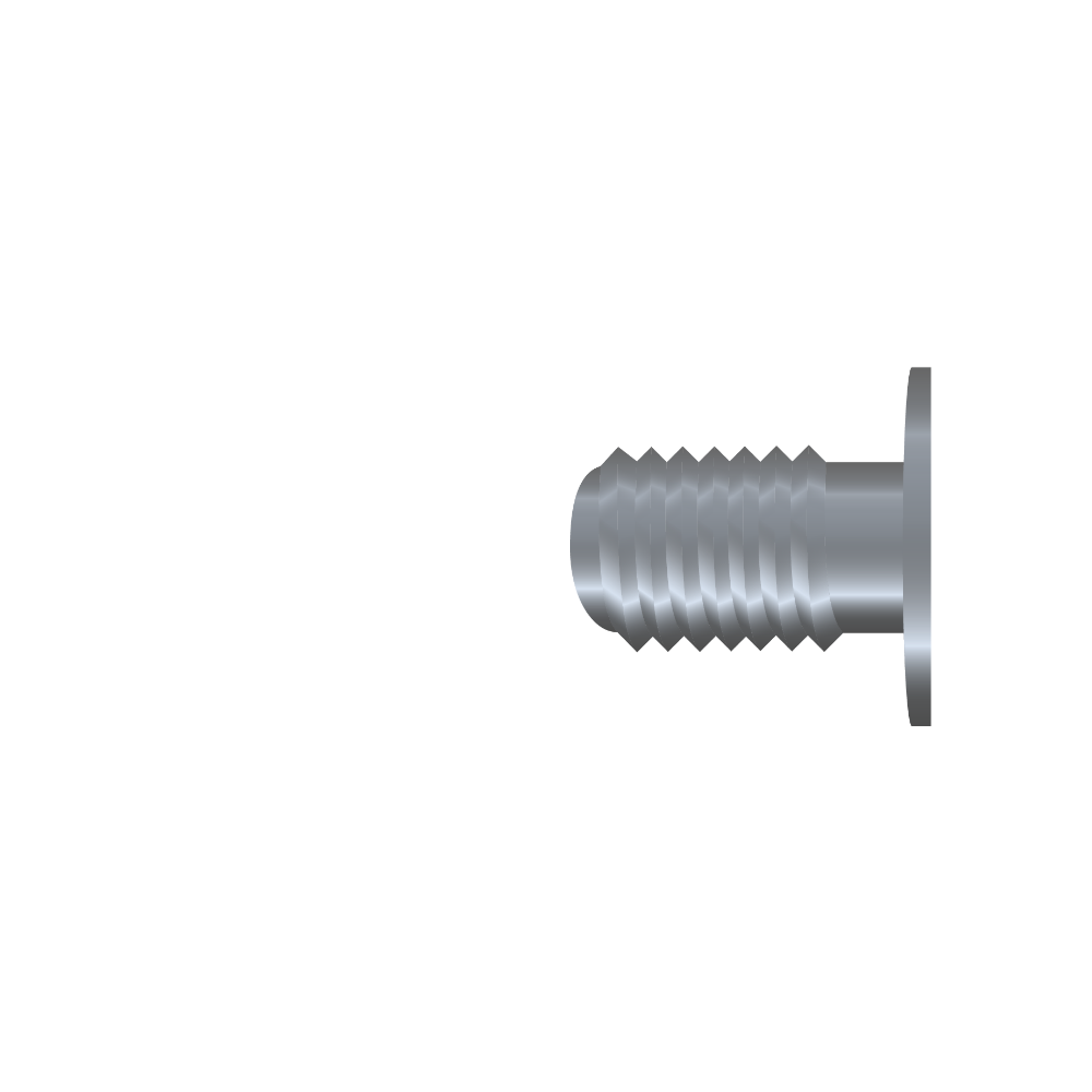
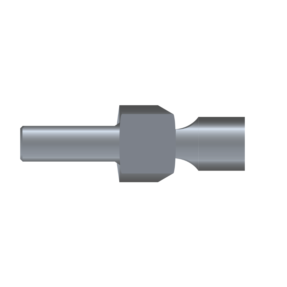
Connecting parts:
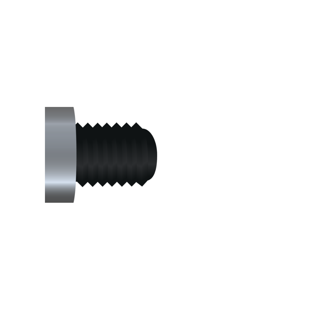
The piston rod is available with the threads MF10x1x18 for piston rod Ø 10 or with MF14x1,5×20 for piston rod Ø 14.
Find the right connection for your gas traction spring
Find the right connection for your gas traction spring
Details
Possible article no.:
K0 B1 Z K 3 100 338 001* 250N
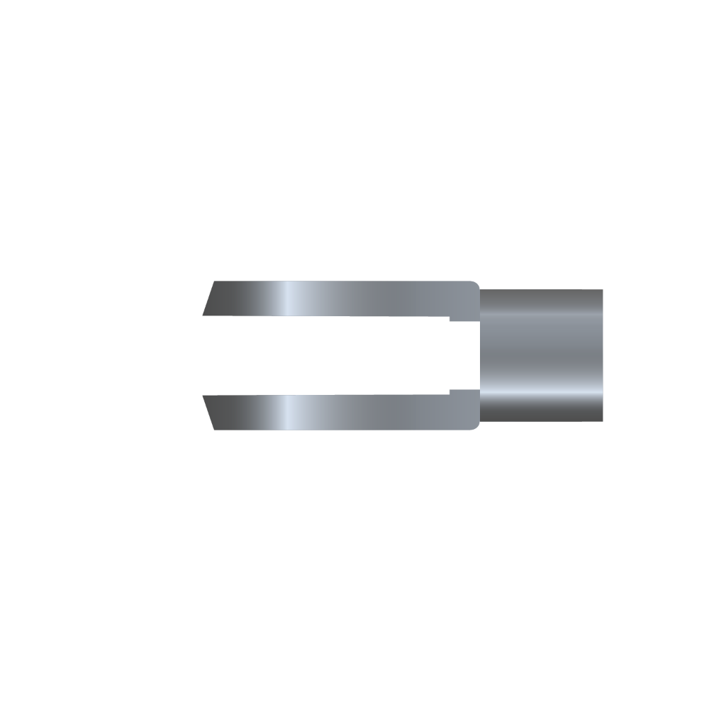
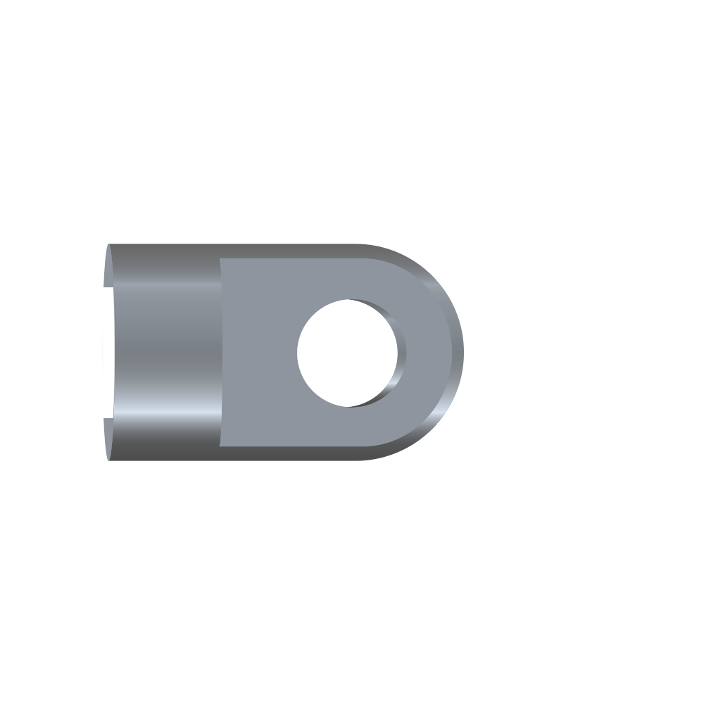
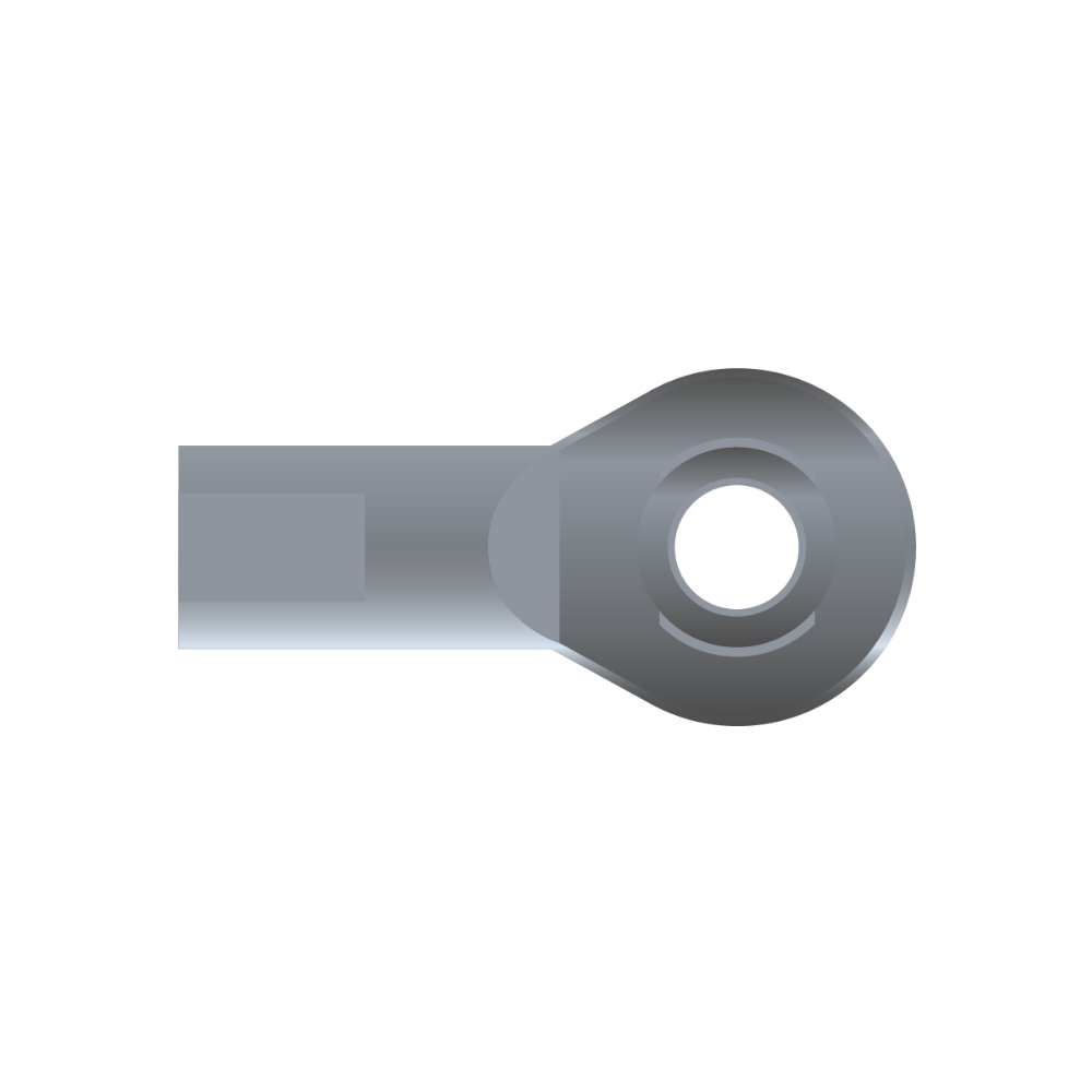
Connecting parts
piston rod
piston rod
K0
- K0 = MF 10x1x18
- O0 = MF 14×1,5×20
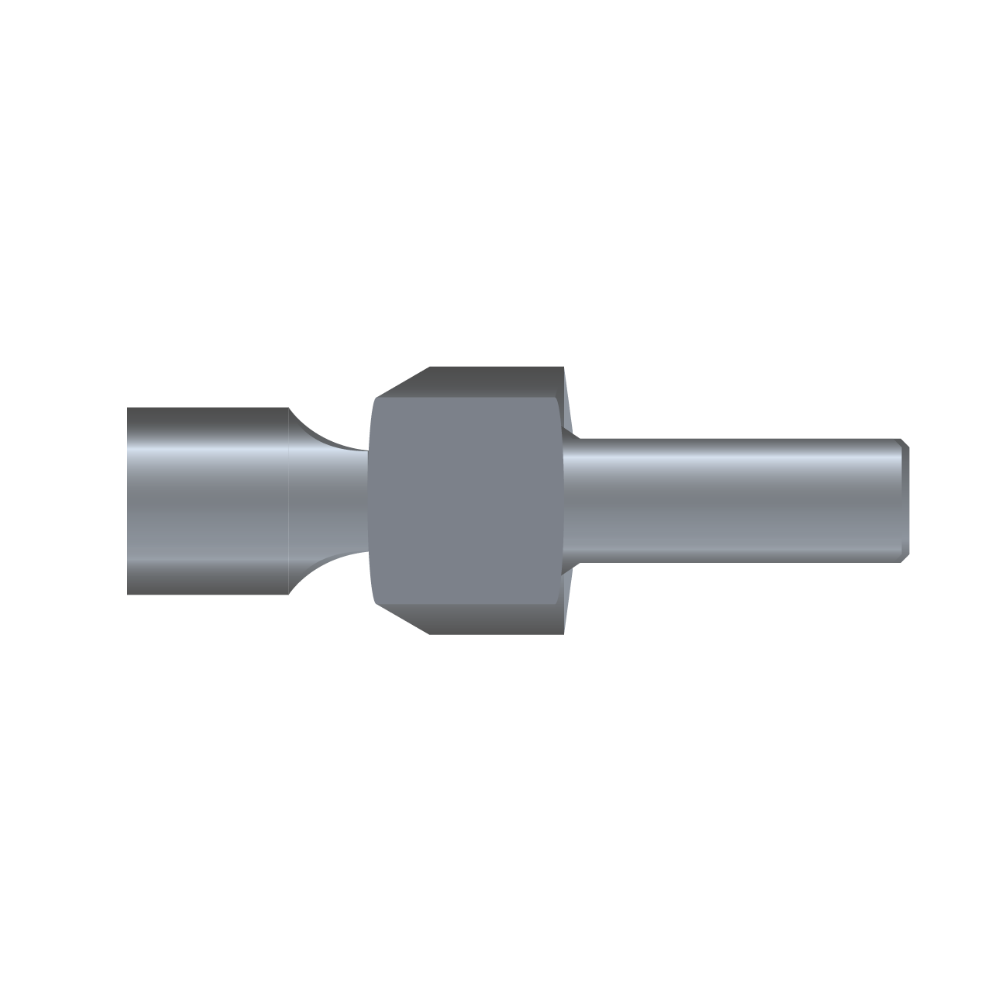
Connecting parts
cylinder
cylinder
B1
- see connecting parts
Model
Z
- ZK
Push-out speed / damping
K
- As for lockable gas springs
Diameter piston rod / cylinder
Øx/Øy (mm)
3
- 3 = 10/28
- B = 14/40
Stroke
A (mm)
100
- 10-350
- As required
Extended length
min. EL2 (mm)
338
- 3 = 2x Stroke + 126 mm
- B = 2x Stroke + 141 mm
Index Number
001*
- * see below
Force (N)
250N
- Pulled-in = 100-4000N
- As required, measured 5 mm before inserted position, force range depends on size
- 3= 100-1500N
- B= 200-4000N
- Traction force: extended + approx. 65% higher if stroke >100mm, stroke <100mm on request
Locking
force in push
direction
force in push
direction
(N)
- 7.000
Locking
force in push
direction
force in push
direction
(N)
- 7.000
* Index Number
With the index no. – only necessary for repeating orders – we can reproduce exactly the same gas spring which has already been produced. You will receive the index no. with the order confirmation / invoice.
** Attention: Calculation of extended length
EL1
The total length is calculated when the piston rod is inserted. Please add the length of the connecting parts in order to find out the total length.
EL2
Length EL2 = measured without hinge eyes and threads.
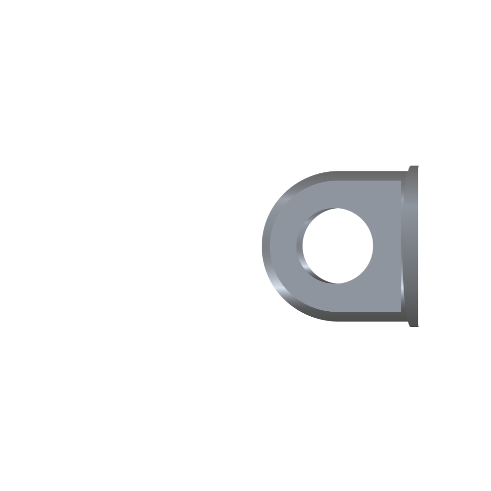
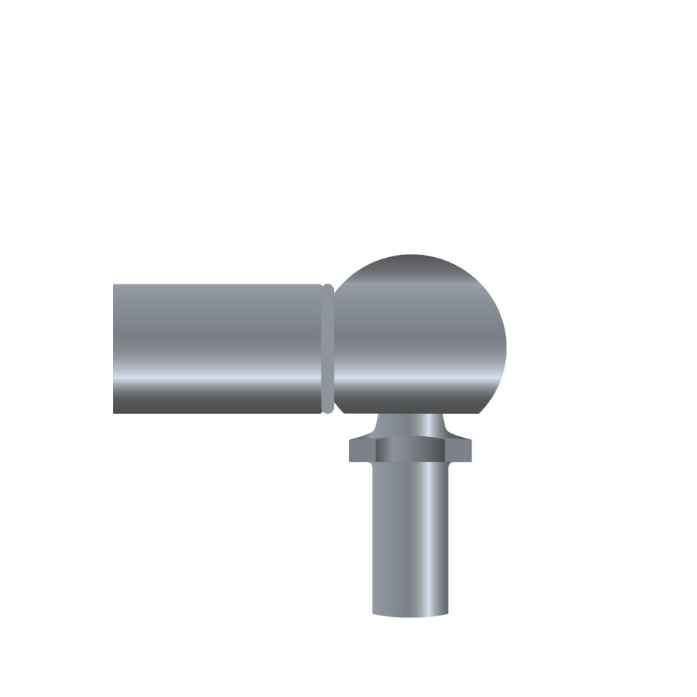
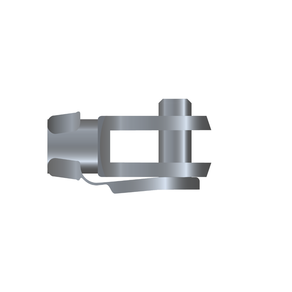
Connecting parts
Bansbach connecting parts
Choose your connecting part.


Code
A1
B1
J2
L2
N2
Z2
SW
10,0
12,0
8,20
12,0
10,0
12,0
Ø
8,2
8,2
8,2
10,2
8,2
12,2
L2
16,0
13,0
16,0
13,0
13,0
12,0
L4
15,0
12,0
15,0
12,0
12,0
12,0
Ø1
15,0-17,0
20,0
15,0-17,0
20,0
20,0
20,0
d2
19,0-22,0
28,0
19,0-22,0
28,0
28,0
28,0
Material
Aluminium
Aluminium
Aluminium
Aluminium
Aluminium
Aluminium


Release systems
Bansbach release systems
Choose an release system.
Release System With Lever


Bowden Wire Release System


Hydraulic Release System


Release lever in “function”

- 1Gas spring release head standard
- 2Pivot point
- 1aRelease lever (release direction towards spring)
- 2aRelease lever (release direction towards the spring)
- 1bRelease lever (release direction away from spring)
- 2bRelease lever (release direction away from spring)
Flat grip for release lever

Standard release head for bowden wire


type of
construction
construction
- 20AK08M8*1
- 20AK08M10*1
- 20AKXXMXX
- 20AK10M10*1
- 20AK12M10*1
- 20AK12M14*1,5
- 20AK14M14*1,5
max. load
inpull direction
inpull direction
- 7.000
- 7.000
- 7.000
- 12.000
- 12.000
- 12.000
- 12.000
A mm
- 37
- 37
- 37
- 54
- 54
- 54
- 54
B mm
- 30
- 30
- 30
- 39
- 39
- 39
- 39
C mm
- 38
- 40
- 40
- 50
- 50
- 50
- 50
D mm
- R8,5
- R8,5
- R8,5
- R14
- R14
- R14
- R14
D1 Ø mm
- 8,1-0,05
- 8,1-0,05
- 10,1-0,05
- 10,1-0,05
- 12,1-0,05
- 12,1-0,05
- 14,1-0,05
E Ø mm
- 17
- 17
- 17
- 21
- 21
- 21
- 21
F mm
- SW11
- SW11
- SW11
- SW14
- SW14
- SW14
- SW14
G mm
- 20
- 20
- 20
- 26
- 26
- 26
- 26
H mm
- 38.5
- 38.5
- 38.5
- 53
- 53
- 53
- 53
M1 mm
- M8*1
- M10*1
- M10*1
- M10*1
- M10*1
- M14*1.5
- M14*1.5
Nut (SW)
- SW13
- SW17
- SW17
- SW17
- SW17
- SW19
- SW19
At screwed depth mm
- 9
- 9
- 7
- 8
- 8
- 8
- 8


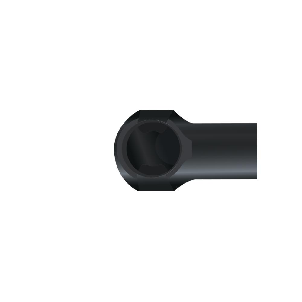
Brackets
Bansbach Brackets
Here you will find your brackets.
900BA1SB


900BA2SB


900BA5SB


900BA3


900BA4


900BA6BO


900BA12SR


900BA14SR


900BA20SR


900BA21SR


Downloads


Recommendation for installation
Bansbach Recommendation for installation
Just like other technical systems that have to do with force development, the application of easylift gas springs requires the knowledge and observance of some data and facts. The essential criteria can be found on this page. Of course, when discussing your application, our consultants will go into detail about all the technical issues that are important to you. This is already routine for our regular customers.
The installation recommendations can be changed in the sidebar.reits Routine.
The installation recommendations can be changed in the sidebar.reits Routine.
-
Within the ranges shown, you can select your optimum dimension yourself. The tolerance for the installation lengths is generally ± 2.5 mm, within a series production a manufacturing tolerance of max. ± 1 mm applies. For high demands on durability and stability, please avoid the combination: small diameter + long stroke + high force.
-
Damping characteristics can generate vibrations that find a resonant body in the application, causing noise. Small changes to the installation, fasteners or tuning can remedy the situation.
-
Bansbach gas springs have been designed and tested for the highest requirements and greatest possible reliability. Installation recommendations and our comprehensive advice will support you in the selection of your individual gas springs.
But: The suitability test for the respective application is always the responsibility of the user! Products which are unsuitable for the application and defective products must not be used. We therefore exclude any liability for the functionality and service life of your end product.
-
Bansbach gas springs are manufactured to order – from mostly stock components. Cancellation, subsequent modification, exchange or return is therefore not possible.
-
If gas springs are sent in for detailed inspection, this constitutes consent to the destruction of this part, and the right of ownership thereby expires. Return of individual components is not possible. If necessary, mark submissions with e.g. “For functional test and with request for return”. If there is no objection, gas springs sent in will be disposed of 1 week after notification of the test result.
As a general rule: For unjustified complaints we reserve the right to charge a lump sum or the actual costs for processing and disposal.
-
Warranty claims expire in principle no later than 1 year after the date of manufacture of the gas spring. Manufacturing defects or quality defects in the gas spring can be detected immediately. If you are not satisfied with the delivered quality of the gas spring for a particular reason, please return it immediately. Please enclose the reason and an original copy of the invoice!
-
Bansbach gas springs can be stored in any position. Pressure loss of the gas spring due to long storage is not to be expected. No negative empirical values are available. However, sticking effects can occur, which require a higher effort when the gas spring is actuated for the first time (breakaway force).
-
The piston rod must be protected from impact, scratches and contamination – especially paint application. The cylinder tube must not be deformed. Damage to the surface will destroy the gas spring sealing system.
-
Gas springs are maintenance-free. Do not grease or oil the piston rod.
-
If gas springs are damaged visibly (broken or deformed connecting parts, bended piston rod, dented cylinder) due to external cause (accident, collision, extreme overloading,…) the pressure has to be released before the gas spring is being dismantled or used.
Please note our disposal and recycling instructions!
-
Gas springs should not be exposed to any tilting or sideforces during operation. If this is unavoid able, please check the installation and use suitable connecting parts.
-
Gas springs should be installed with the piston rod downwards. This position ensures the best damping effect. Only Bansbach gas springs include an integrated grease chamber which allows different directions of installation.
-
Bansbach gas springs can be used generally as a limit stop in both directions. The occuring forces should not exceed the following approximate values.
Series- 3/8
- 3/10
- 4/12
- 6/15
- 6/15 Niro
- 6/19
- 8/19
- 8/19 Niro
- 8/20 Alu
- 8/22
- 8/28
- 10/22
- 10/22 Niro
- 10/28
- 10/28 Niro
- 10/40
- 12/28
- 12/40
- 14/28
- 14/28 Niro
- 14/40
- 16/28
- 20/40
max. Force (N)- 600
- 600
- 1.500
- 2.500
- 1.750
- 2.000
- 5.000
- 3.000
- 3.500
- 5.000
- 7.000
- 5.500
- 3.000
- 8.500
- 6.500
- 7.000
- 9.250
- 12.500
- 7.000
- 7.000
- 6.250
- 15.000
- 10.000
This isn’t valid for lockable gas springs and traction springs!
Attention: The figures refer to the average pressure range of the respective size.
Some connectors such as elbow joints may not be suitable for the above values.
In case of high limit stop forces as well as for permanent load, we recommend an additional mechanical limit stop.
In case of reaching the limit range or a permanent use as limit stop please contact Bansbach easylift.
-
All gas springs are labeled with the warning „Do not open, high pressure“, the part number and the production date. If these dates are unreadable (removed, painting of the gas springs or any other influences) we refuse the liability for damages which result from this fact. Warranties aren’t possible anymore.
-
Disposal / recycling: Gas springs are mainly made of metal and can be recycled. However, the gas springs must be depressurised beforehand. Please request our disposal instructions for gas springs.
-
Gas springs are filled with pure nitrogen. Nitrogen is an inert gas, does not burn, does not explode and is not toxic. However: gas springs have a very high internal pressure (up to approx. 300 bar). Gas springs must never be opened without instructions!
-
Bansbach gas springs can be used at ambient temperatures from -30℃ to +80℃. For other temperature ranges (down to -55℃ or up to +200℃) special seal sets are available. For low-temperature ranges, detailed coordination of the requirements is necessary. The ambient temperature has an influence on the gas spring characteristics. Changes in extension force as well as damping characteristics are to be expected and should be tested in advance under application conditions. Do not overheat gas springs or place them in an open fire! Other environmental conditions can also have a significant influence on the service life. Please take protective measures into consideration.
Any questions about our gas springs, dampers etc.?
We are here for you!
To the contact personWith Bansbach easylift,
the product is adapted precisely to your requirements to ensure optimum function. We are happy to support and advise you in selecting the right product, from simple gas springs to special pneumatics.
With our “Technical Support” you have a direct line to our technicians, who will provide you with competent assistance. If you have any questions about offers, availability or prices, our commercial support team will be happy to assist you.

Step by step to the individual product
We build your gas spring!
The Bansbach gas spring configurator offers
you the possibility to put together your individual
gas spring from various components
even more easily and quickly.

Bansbach easylift
Stainless steel – Products
- » High-quality stainless steel material (V4A, AISI No. 316L)
- » Water resistant
- » Suitable for food, chemical and seawater applications
- » Connecting parts also made of stainless steel
Bansbach
Quality
Bansbach products are manufactured exclusively from high-quality, environmentally friendly materials. By continuously monitoring raw materials, carrying out test programmes and monitoring quality during the manufacturing process, consistently high quality can be guaranteed.


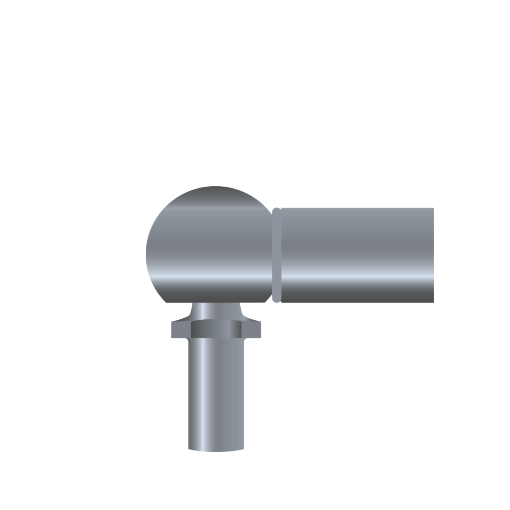
High-quality connecting part
End piece available in different versions

Cylinder
Cylinder made of steel, powder-coated or high-quality stainless steel

Piston
High-quality piston for speed control

Guiding piece
High-quality, unique guide piece with integrated grease chamber

Piston rod
Cerampro® piston rod extremely durable and corrosion resistant

Connecting part
Connection part available in different versions
Applications examples
Here you will find our products.


FAQs
Are Bansbach gas springs ROHS compliant?
Yes, they are fully ROHS compliant and also meet all guidelines, export/import regulations and goals of other company programs that we are aware of.
Can a gas spring made to customer specifications be returned?
Bansbach gas springs are manufactured to order – from mostly stock components. Cancellation, exchange or return is therefore not possible.
In case of free delivery, we will gladly take over the disposal – without charge – for you.
Can gas springs be disposed of in household waste?
No, gas springs are mainly made of metal. Please observe our disposal instructions.
Can gas springs be used in the food industry?
With the high-quality stainless steel gas springs in V4A, the high requirements of the food industry are met. Food-grade oil (FDA oil) is optionally available.
Can the speed/damping of the gas spring be influenced?
By selecting the appropriate nozzle bore and oil viscosity, the speed and damping of the gas spring can be adapted to the application.
Do Bansbach gas springs have to be stored with the piston rod pointing downwards?
Bansbach gas springs can be stored in any position.
Does a gas spring need to be protected from dirt?
The piston rod must be protected against impact, scratches and contamination – especially paint application. Damage to the surface will destroy the sealing system. If necessary, a wiper or a protective tube should be provided.
Does a gas spring need to be serviced?
No, Bansbach gas springs are maintenance-free. The piston rod must not be greased or oiled.
How do I find my personal contact person?
Bansbach easylift GmbH
Bararossastrasse 8
D-73547 Lorch
Phone: +49 (0) 7172/9107-0
Fax: +49 (0) 7172/9107-44
E-Mail: info@bansbach.de
You can find a contact person on site
Contact form
How high can the internal pressure of a gas spring be?
Depending on the series and the desired extension force, this can be up to approx. 300 bar.
How much is the weight of a gas spring?
Due to the wide range of products, the weights vary greatly.
Diameter piston rod / cylinder:
Ø3/8; Ø4/12; Ø6/15; Ø6/19; Ø6/22; Ø8/19; Ø8/22
Weight
100 g – 500 g
———-
Diameter piston rod / cylinder:
Ø8/28; Ø10/22; Ø10/28; Ø12/28; Ø14/28
Weight
200 g – 1000 g
———-
Diameter piston rod / cylinder:
Ø16/28; Ø10/40; Ø12/40; Ø14/40; Ø20/40; Ø30/70
Weight
500 g – 8000 g
In which colors are Bansbach gas springs available?
The piston rod and the cylinder are supplied in black (standard).
On request, our cylinders are available in all RAL colors. Exception: stainless steel
In which temperature ranges can Bansbach gas springs be used?
For ambient temperatures from -30°C to +80°C.
For other temperature ranges (down to -55°C or up to +200°C) special seal sets are available.
Is it possible to repair a gas spring?
No, because it is a closed system that is under high pressure and must not be opened.
Is the extension force of the gas spring temperature-dependent?
For physical reasons, the extension force of the gas spring changes by approx. 3.3% per 10°C (base + 20°C).
What does the index number (e.g. – -001/100 N) at the end of the article designation of the gas spring mean?
This is a code assigned internally by Bansbach for unambiguous reproducibility of the gas spring.
What materials are Bansbach gas springs made of?
Gas springs consist of piston rod, cylinder tube, connecting parts, turned parts, seals, oil, grease and nitrogen. Piston rods and cylinder tubes are made of steel and are CeramPro® or powder coated in our company. Connecting parts and turned parts are made of lead-free steel or lead-free aluminum.
Seals, oils, greases do not contain substances that are on the list of critical or hazardous substances. Nitrogen is an inert gas that neither burns nor poses any other health hazards. Bansbach gas springs therefore comply with current and, as far as we know, planned laws and regulations.
They comply for example with the RoHS Directive, WEEE Directive, Directives 2003/11/EC, 2002/95/EC, 2002/96/EC. They are not covered by Directives 94/9/EC, 97/23/EC, and 98/37/EC, nor by UN 3164, TRGS 220, and UL 60601-1.
Verification that Bansbach gas springs in the end product comply with national or international laws and regulations remains the responsibility of our customers or the user.
What service life/running performance can I expect from a Bansbach gas spring?
On average, Bansbach gas springs are designed for 50,000 – 100,000 double strokes.
Depending on the design, installation and effective stroke, several 100,000 strokes can also be achieved.
For other products please contact us.
Which stroke lengths are possible for the gas springs?
Depending on the series and design of the gas spring, the stroke length can be freely selected between 10 mm and 1000 mm. Other variations possible, please contact us.

With our “Technical Support” you have a direct line to our technicians, who will competently assist you. If you have questions about offers, availability or prices, our commercial support will be happy to assist you.
